

Custom Injection Moulds for Electrical Shells
1. Product Introduction – Precision Moulds for Electronic Enclosures
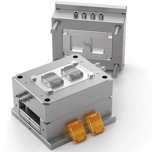
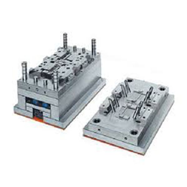
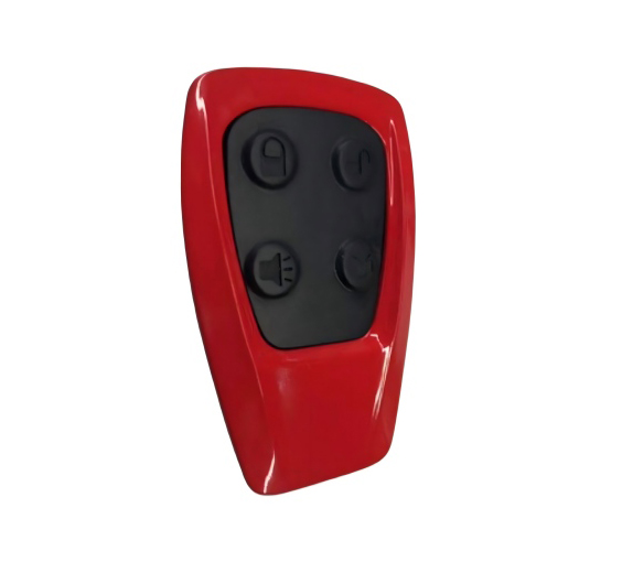
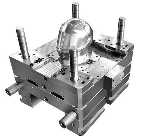
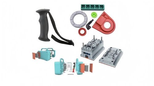
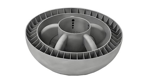
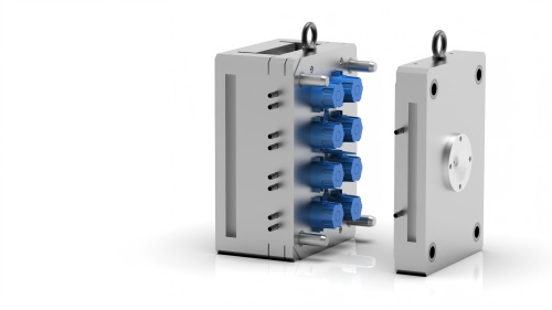
Our Custom Injection Moulds for Electrical Shells are precision tooling systems designed to produce high-quality plastic enclosures for electronic and electrical applications. From power supply housings and control units to sensor shells and consumer electronics cases, these moulds deliver consistent dimensional accuracy, clean aesthetics, and reliable performance.
Electrical shells present unique challenges: they require precise alignment for PCB mounting, secure snap-fits or screw bosses, proper ventilation, and often EMI/RFI shielding compatibility. Our moulds are engineered to meet these demands with advanced cooling, balanced runner systems, and durable steel construction.
Whether you need shells for industrial controllers, battery management systems, smart home devices, or medical electronics, our custom moulds deliver parts that fit perfectly, assemble easily, and perform reliably.

2. Key Benefits – Why Choose Our Electrical Shell Moulds?
| Benefit | Description |
|---|---|
| Precision Tolerances | ±0.02mm ensures perfect PCB alignment, connector fit, and screw boss placement |
| Design Integration | Mould in mounting posts, snap-fits, EMI shielding grooves, and cable clips |
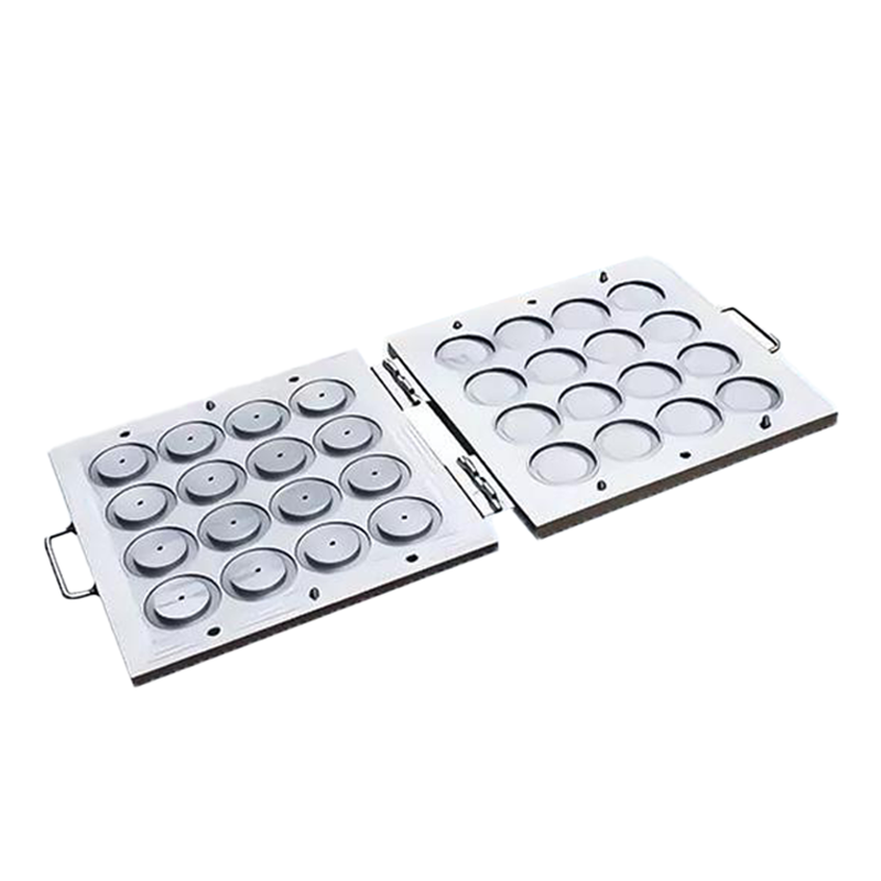
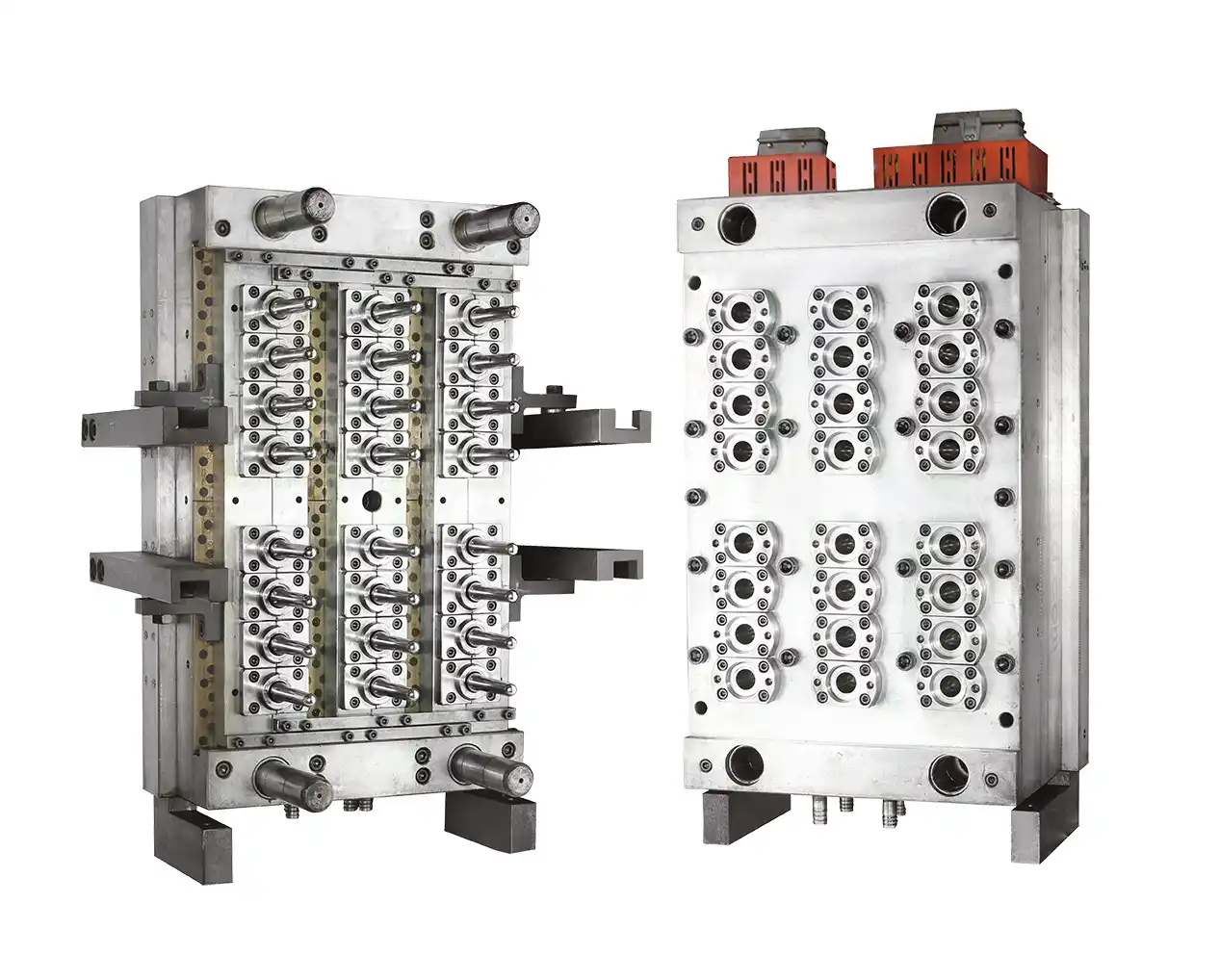
| Multi-Cavity Options | 2, 4, 8, or 16 cavities for high-volume shell production |
| Fast Cycles | Optimized cooling reduces cycle time by 15–30% |
| Durable Construction | P20, H13, or stainless steel – 500,000 to 1,000,000+ cycles |
| Cost Efficiency | Lower per-part cost through multi-cavity moulds and reduced scrap |
For electrical shell applications ranging from small sensors to large control panels, our moulds deliver the perfect balance of precision, durability, and productivity.
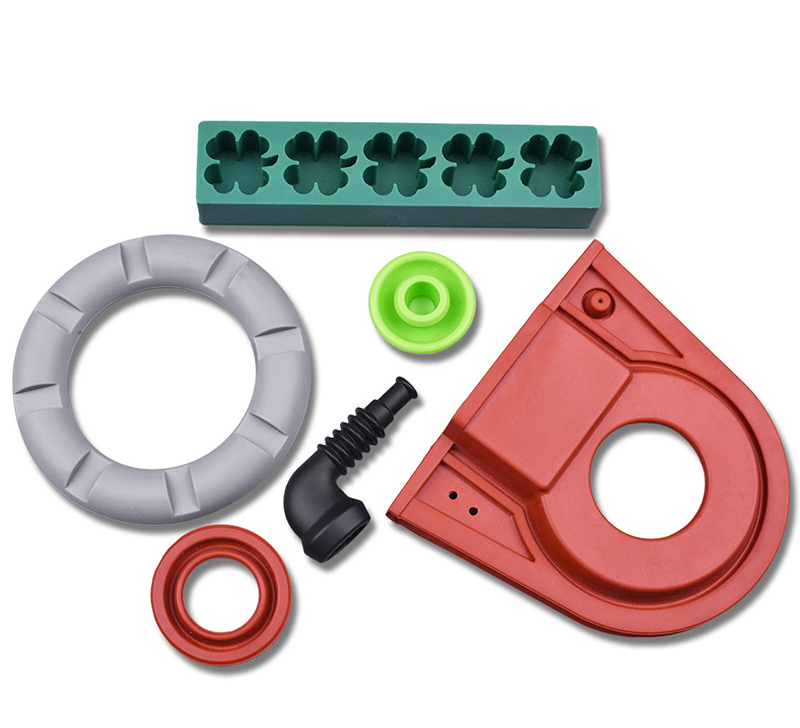
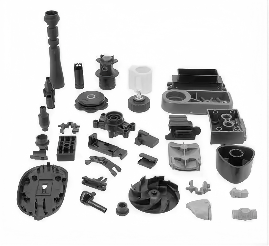
3. Types of Electrical Shells We Mould – Applications Across Industries

| Industry | Shell Type | Key Features |
|---|---|---|
| Power Electronics | Power supply housing, inverter shell, converter enclosure | Ventilation slots, screw bosses, UL94 V-0 compatibility |
| Industrial Control | PLC housing, relay shell, HMI enclosure | DIN-rail clips, terminal access ports, EMI shielding |
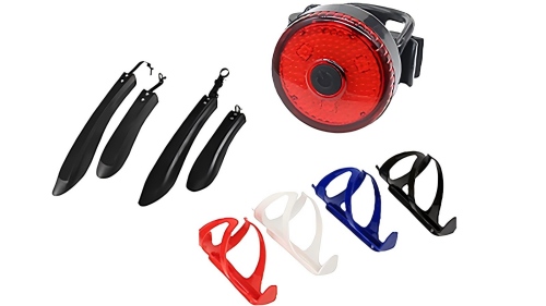
| Consumer Electronics | Smart home hub, router shell, set-top box case | Aesthetic surface, snap-fit assembly, LED light pipes |
| Battery & Energy | BMS enclosure, battery management shell, charger housing | Gasket groove, flame-retardant materials, thermal vents |
| Medical Electronics | Monitor shell, diagnostic device housing, pump enclosure | Cleanability, biocompatible material support |
| Automotive Electronics | ECU housing, sensor shell, infotainment case | Vibration resistance, IP-rated sealing, high-temperature materials |
4. Custom Design Features – What We Can Integrate Into Your Shell Mould
Our moulds are designed to accommodate a wide range of shell-specific features:
4.1 Mounting & Assembly Features
| Feature | Description | Typical Application |
|---|---|---|
| Screw bosses | Reinforced posts for screw assembly | Top/bottom shell joining |
| Snap-fits (cantilever or annular) | Tool-free assembly | Battery covers, consumer electronics |
| PCB mounting posts | Precise standoffs for circuit boards | All electrical shells |
| DIN-rail clips | Integrated mounting for industrial panels | Control units, power supplies |
| Cable management clips | Wire routing and strain relief | Sensor housings, junction boxes |
4.2 Protection & Shielding Features
| Feature | Description | Best For |
|---|---|---|
| EMI / RFI shielding groove | Accommodates conductive gaskets or spring fingers | Sensitive electronics, medical devices |
| Gasket groove | For O-ring or silicone seal | IP-rated enclosures |
| Ventilation slots | Passive cooling for heat-generating components | Power supplies, chargers |
| Pressure relief valve port | For sealed enclosures | Battery shells, outdoor electronics |
4.3 Cosmetic & Interface Features
Logo / text recess – Branding, model numbers, safety labels
LED light pipe cavity – For status indicators
Connector cutout / port opening – USB, RJ45, power inlet
Vent / membrane port – For pressure equalization (outdoor shells)
4.4 Surface Finishes for Electrical Shells
| Finish | SPI Code | Best For |
|---|---|---|
| High gloss | A1, A2 | Consumer electronics, visible shells |
| Matte | B1, B2 | Professional equipment, anti-glare |
| Texture (leather, grain) | D1, D2, D3 | Grip surfaces, hiding flow lines |
| EDM texture | VDI 12–45 | Industrial shells, cost-effective |
5. Material Options for Electrical Shells – Matching Material to Application

| Material | Key Properties | Best Electrical Shell Applications |
|---|---|---|
| ABS | Good impact strength, economical, paintable | Consumer electronics, general enclosures |
| PC (Polycarbonate) | High impact strength, transparent options | Medical devices, clear shells |
| PC/ABS Blend | Balanced toughness, heat resistance, UL94 V-0 available | Power supplies, BMS enclosures |
| UL94 V-0 Grades (ABS, PC, PC/ABS) | Flame-retardant, self-extinguishing | Battery shells, industrial electronics |
| Nylon (PA6/PA66) | High strength, chemical resistance | Industrial connectors, heavy-duty shells |
| Nylon + GF (glass-filled) | Rigid, high heat deflection | Automotive electronics, under-hood |
| Conductive / Anti-static | Dissipates static charge | Cleanroom electronics, explosive environments |
| PCR (Post-consumer recycled) | Sustainable option | Eco-conscious consumer products |
Our recommendation for electrical shells: PC/ABS UL94 V-0 for flame-retardant requirements, ABS for cost-sensitive visible shells, and Nylon+GF for high-strength industrial applications.
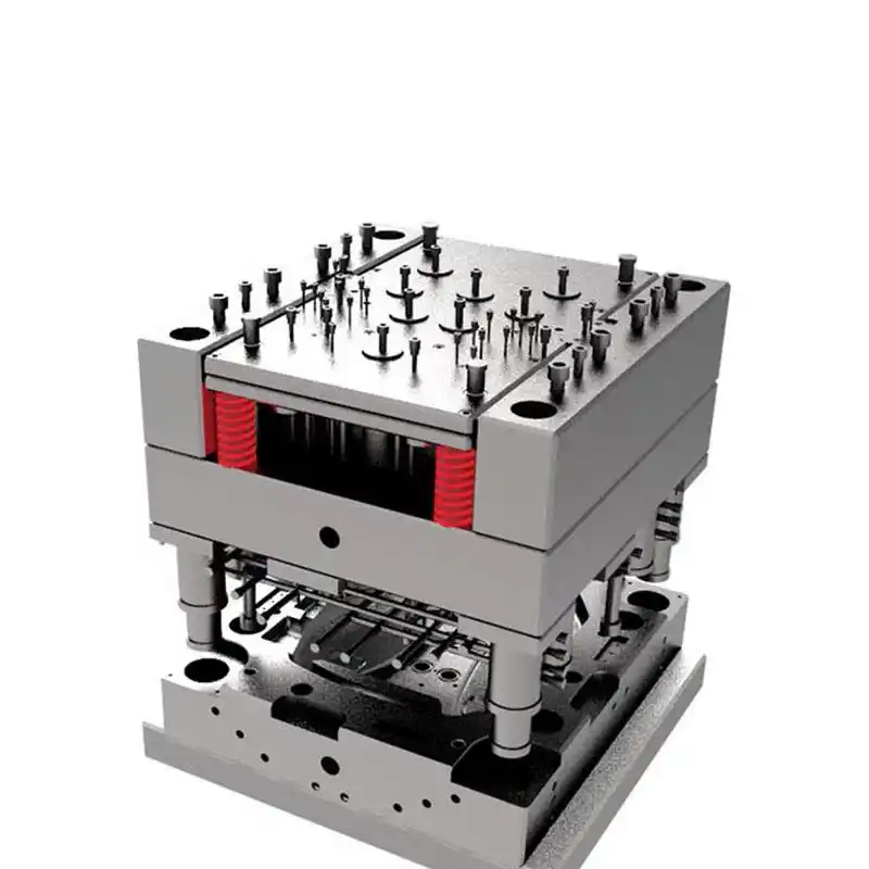
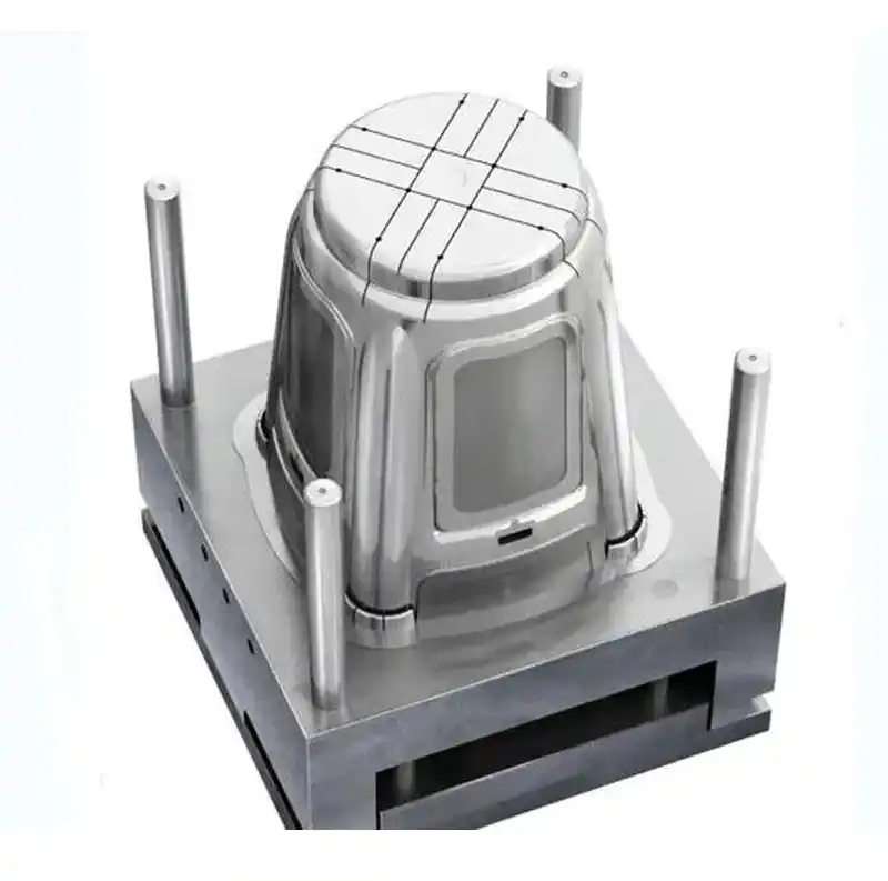
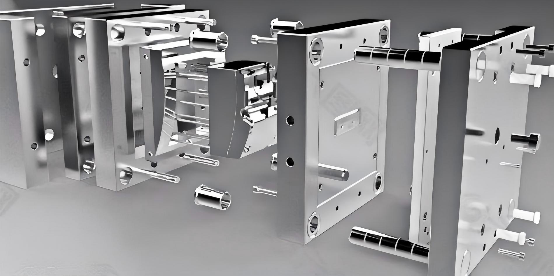
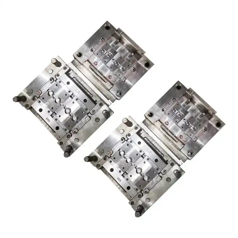
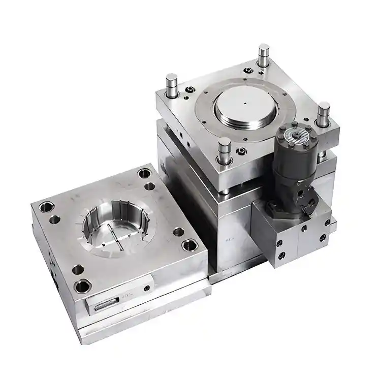
6. Mould Construction – Built for Precision and Long Life
6.1 Cooling System – Critical for Flat, Warpage-Free Shells
Electrical shells require flat sealing surfaces and straight walls. Our cooling design prevents warpage:
Conformal cooling – Cooling channels follow the shell contour
Baffles & bubblers – For deep shell cavities and core pins
Uniform temperature distribution – Delta T < 5°C across cavity
Cycle time reduction – 15–30% faster than standard layouts
6.2 Ejection System for Electrical Shells
| Ejection Method | Best For |
|---|---|
| Ejector pins | Simple shell geometries, hidden under PCB |
| Stripper plate | Thin shells, fragile features, cosmetic surfaces |
| Air ejection | Deep shells with no visible marks |
| Robot pick-out | Fully automated production |
8. Manufacturing Process & Quality Control

8.1 Mould Manufacturing Steps
| Step | Description | Duration |
|---|---|---|
| 1. Design & DFM | 3D modelling, mould flow analysis, gate location optimization | 3–5 days |
| 2. Steel preparation | Cutting, heat treatment (if required) | 3–5 days |
| 3. CNC machining | 3/5-axis milling, EDM for fine details | 2–4 weeks |
| 4. Fitting & assembly | Core/cavity fit, ejector system, cooling | 1 week |
| 5. Polishing & texturing | SPI finish, logo engraving, texture | 3–5 days |
| 6. Testing | Dry cycle, cooling pressure test, sample moulding | 2–3 days |
8.2 Quality Inspection Checklist for Electrical Shell Moulds
✅ Cavity/core dimensions (CMM, ±0.01mm)
✅ Screw boss position and depth (critical for PCB mounting)
✅ Snap-fit dimensions and undercut clearance
✅ Surface finish verification (roughness tester)
✅ Cooling circuit flow & pressure test
✅ Ejector system function (smooth travel, no binding)
✅ Gate and runner dimensions
✅ Hardness check (for production steels)
✅ Sample part inspection (flatness, warpage, fit with PCB)
9. Project Workflow – From Concept to Production
5-step process diagram – Design → Mould Manufacturing → Sampling → Approval → Production
Step 1: Design Review (3–5 days)
You provide: Electrical shell 3D model (STEP/IGES/STP), material, target volume, PCB dimensions, mounting requirements
We provide: DFM report, gate location proposal, cavity count recommendation, screw boss and snap-fit optimization, firm quote
Step 2: Mould Manufacturing (5–8 weeks)
Steel cutting, CNC machining, heat treatment, fitting, polishing
Weekly progress updates with photos
Step 3: Sampling & Validation (2–3 days)
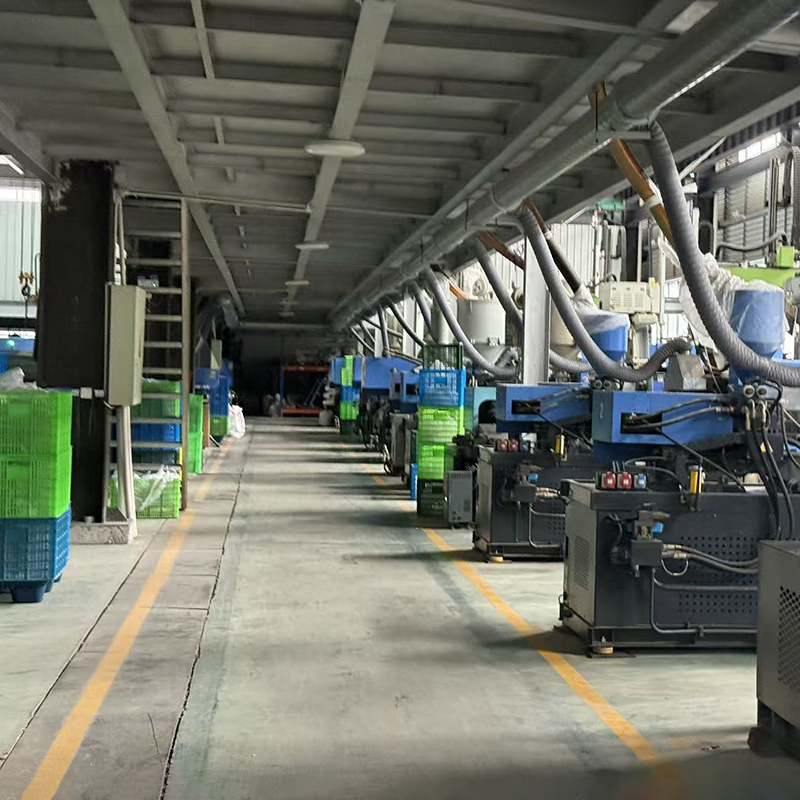
Sample shells moulded on our in-house machines
Dimensional report, flatness measurement, PCB fit test
20–50 sample shells shipped to you
Step 4: Customer Approval (1 week)
You test fit with PCB, connectors, and mating shell
Test snap-fit engagement and screw assembly
Any minor adjustments made at no charge
Step 5: Production or Delivery
Mould shipped with spare parts kit and maintenance manual
Or we run production shells for you (moulding service available)
Total lead time: 6–9 weeks typical for a production electrical shell mould
10. Technical Specifications – Complete Reference
| Parameter | Range / Options |
|---|---|
| Mould type | Two-plate or three-plate |
| Cavity count | 1, 2, 4, 8, 16, or custom |
| Mould steel | P20, H13, 420 stainless, or aluminium (prototype) |
| Shell size range | 20mm to 400mm+ |
| Wall thickness | 1.0mm – 3.5mm (typical) |
| Typical tolerance | ±0.02mm – ±0.05mm |
| Surface finish | SPI A1 (high gloss) to SPI D3 (matte/textured), VDI textures |
| Gate types | Edge, tunnel, fan, pin-point |
| Runner system | Cold runner (standard) or hot runner |
| Cooling | Straight channels, baffles, conformal |
| Ejection | Pins, stripper plate, or air |
| EMI shielding capability | Groove for gasket or conductive coating compatible |
| IP rating support | Gasket groove for IP54–IP67 |
| Expected mould life (P20) | 500,000+ cycles |
| Expected mould life (H13) | 1,000,000+ cycles |
| Lead time | 6–9 weeks |
| Warranty | 12 months on workmanship and materials |
11. Why Choose Us for Your Electrical Shell Moulds?
With over 15 years of experience in injection mould manufacturing — including hundreds of electrical shell moulds shipped worldwide — we offer:
Electrical shell expertise – We understand PCB mounting, EMI shielding, snap-fit design, and IP sealing
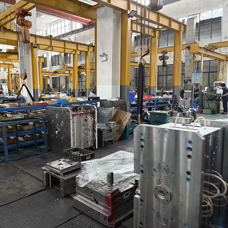
In-house mould design & manufacturing – No outsourcing, full control
Free DFM (Design for Manufacturing) report – We optimize your shell design before cutting steel
Competitive pricing – 20–30% lower than many competitors for equivalent quality
Fast lead times – 6–9 weeks for most production electrical shell moulds
Low MOQ – From prototype (100 shells) to high-volume (1M+ shells/year)
Material verification – We provide UL, RoHS, and REACH compliance documentation
Spare parts kit – Every mould includes ejector pins, springs, and wear parts
Global shipping – Air, sea, or express with secure crating
12. Request a Quote – Start Your Electrical Shell Mould Project Today
Ready to produce high-quality electrical shells with a custom injection mould built specifically for your electronic enclosure?
What we need to get started:
Electrical shell 3D model (STEP, IGES, STP, or hand sketch for early discussion)
Material type and grade (e.g., ABS, PC/ABS UL94 V-0, Nylon+GF)
Estimated annual volume (e.g., 100,000 shells/year)
PCB dimensions and mounting hole locations (if available)
Special requirements (EMI shielding? IP rating? Snap-fit? Live hinges?)
Moulding machine specifications (if known – tonnage, platen size)
What exactly are your OEM services?
Our OEM (Original Equipment Manufacturing) service allows you to bring your unique outdoor gear ideas to life. We handle the entire product development and manufacturing process based on your specifications, designs, and brand requirements. From initial concept and material sourcing to prototyping, production, and quality control, we become your dedicated manufacturing partner. Your brand logo and identity will be applied to the final products.What is your MOQ (Minimum Order Quantity)?
We understand that brands need flexibility, especially when launching new products. Therefore, we offer flexible MOQs, which vary depending on the product complexity, materials required, and customization level. We encourage you to discuss your project with us, and we will do our best to propose a feasible MOQ.Can you help us develop a product from just an idea or a sketch?
Absolutely! We specialize in turning concepts into high-quality, market-ready products. Our product development team will work closely with you to refine your idea, select appropriate materials, create technical drawings, and develop prototypes until your vision is perfectly realized.What are the typical steps in the OEM process with your company?
1.Initial Inquiry & Consultation: You share your concept, target market, and requirements. 2.Quotation & Agreement: We provide a detailed quotation, and once approved, we sign a service agreement. 3.Research & Development (R&D): Our team works on technical designs, material selection, and sample development. 4.Prototyping: We create a physical prototype for your evaluation and feedback. 5. Molds:After design confirming, we will creat mold before production. 5.Sample Approval: You approve the final sample, confirming quality, design, and functionality. 6.Mass Production: Upon your production order confirmation, we begin manufacturing your products. 7.Rigorous Quality Control (QC): We conduct inspections throughout production and a final random inspection before shipment. 8.Shipping & Delivery: We securely pack and arrange shipment to your designated destination.How long does the entire process take from concept to delivery?
The timeline varies significantly based on product complexity and order quantity. A general estimate is: Development & Sampling: 4-8 weeks. Mass Production: 4-6 weeks after sample approval. Please note that this is an estimate, and a precise timeline will be provided with your project quotation.Who owns the intellectual property (IP) and mold/tooling for the custom products?
You retain 100% ownership of your brand identity, designs, and product IP. For any custom molds or tooling created specifically for your project, ownership can be transferred to you upon agreement. We strictly adhere to confidentiality and will never use your designs for other clients.How do you determine the price for an OEM order?
The unit price is determined by several factors, including: Product complexity and design Cost of raw materials Labor and manufacturing processes involved Order quantity Packaging requirements We strive to offer competitive pricing without compromising on quality.What is your quality control process?
Quality is our top priority. Our QC process includes: Incoming Quality Control (IQC): Inspection of all raw materials. In-Process Quality Control (IPQC): Checks during key stages of production. Pre-Shipment Inspection (PSI): A final random inspection of finished products against your approved sample and our quality standards. We can provide detailed QC reports.Can we inspect the products before they are shipped?
Yes. We highly recommend a pre-shipment inspection. You are welcome to send your own QC inspector, or you can hire a third-party inspection company to perform the check at our factory. We can also provide you with photos and videos of the production and final products.How do you handle shipping?
We have extensive experience in shipping outdoor gear globally. We can handle the logistics for you and arrange shipment via sea (for large volumes) or air (for smaller, urgent orders). We work with reliable freight forwarders to ensure a smooth process. Shipping costs will be included in your final quotation.
Related Products