
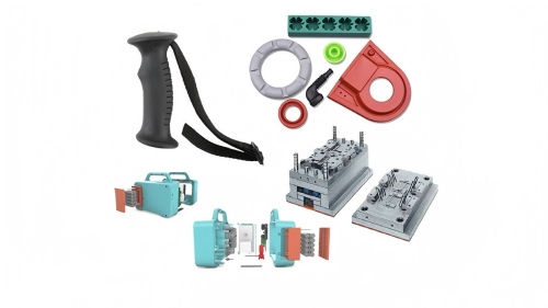


1. What Is “Parting” in Injection Molding?
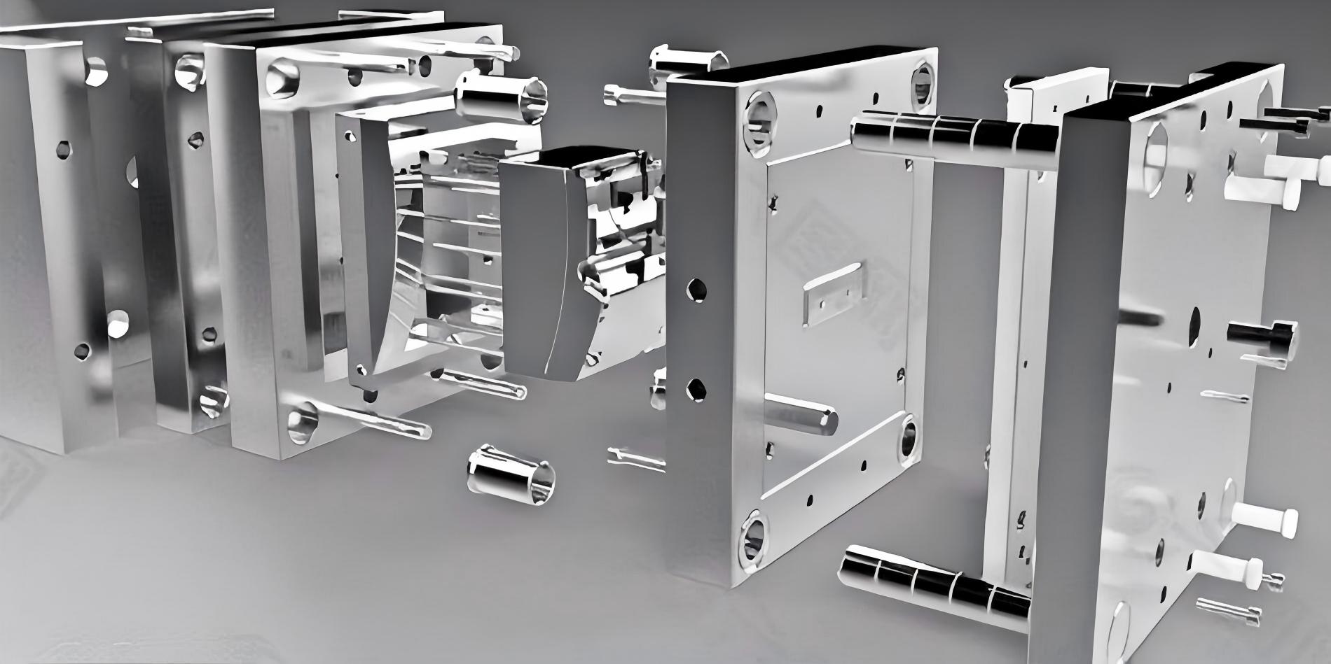
In injection molding, the mold consists of two primary halves:
A‑side (cavity) — fixed to the stationary platen.
B‑side (core) — attached to the moving platen.
The parting surface is the interface where the two halves meet. When the mold opens, the part remains on the core side (B‑side) and is ejected.

Why “splitting” matters:
Defines where the part can have small witness marks (the parting line).
Determines which features need side‑actions (sliders or lifters).
Affects ejection, venting, and cooling layout.
2. Key Factors Before Drawing the Parting Line
Engineers don’t guess the split. They evaluate:
| Factor | Why It Matters |
|---|---|
| Part geometry | Undercuts, holes, bosses, and ribs force complex splitting. |
| Aesthetic surfaces | The parting line should be hidden on edges or non‑visible faces. |
| Draft direction | All vertical walls need draft (taper) to release from the mold. |
| Gate location | The gate (where plastic enters) is often on the parting plane. |
| Ejection | Ejector pins must be placed on the B‑side, not damage critical features. |
| Production volume | High volume justifies more complex split (sliders) to eliminate secondary trimming. |
3. Standard Parting Methods (The “Classic Splits”)
A. Straight (Flat) Parting
The simplest method: the parting surface is a flat plane.
✅ Pros – Low cost, easy to machine, no side actions.
❌ Cons – Only works for parts without side undercuts or deep asymmetries.
B. Stepped Parting
The parting surface changes height (like stairs) to follow the contour of the part.
✅ Pros – Eliminates some side actions, good for parts with offset flanges.
❌ Cons – More complex to CNC machine; requires careful sealing to prevent flash.

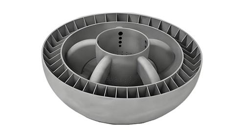
C. Contoured (Curved) Parting
The parting surface follows a 3D freeform curve. Used for sculpted parts (e.g., automotive interior trim, ergonomic handles).
✅ Pros – Hides the parting line on natural styling lines; reduces secondary polishing.
❌ Cons – Expensive machining; tricky to measure and fit.
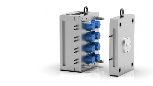
D. Parting with Sliders & Lifters (Complex Splits)
When undercuts exist (e.g., a hole perpendicular to mold opening), the mold must split into more than two main blocks:
Slider – Moves perpendicular to the main opening direction, activated by an angled pin.
Lifter – Moves at an angle inside the B‑side, commonly used for internal undercuts.

4. Step‑by‑Step: How a Designer Splits a Mold in CAD
Using software like NX, Cimatron, or SolidWorks (with Mold Tools):
Import the part and set the pull direction (direction of mold opening).
Analyze draft – Any face with 0° draft fails.
Identify undercuts – Use software’s “undercut analysis” tool (color‑coded faces).
Define parting line – The boundary between core and cavity. Typically along the maximum contour perpendicular to pull direction.
Create parting surface – Extend the parting line outward to the mold base boundary.
Split the mold – Boolean subtract: core & cavity bodies.
Add sliders/lifters for remaining undercuts.
📌 A decision matrix for parting method
| Part Feature | Recommended Split | Added components |
|---|---|---|
| No undercuts, flat top | Flat parting | None |
| Holes parallel to opening | Flat parting (use core pins) | Core pins |
| Simple step change | Stepped parting | None |
| Side hole (perpendicular to opening) | Flat parting + slider | Slider (1 or 2) |
| Internal clip (undercut) | Flat parting + lifter | Lifter |
| Complex organic shape | Contoured parting | None (if no undercut) |
5. Real‑World Case: A Drone Arm
Situation: A drone arm with a battery clip (undercut) on the inside and smooth external surface.
Approach:
Pull direction = vertical (Z‑axis).
Parting line hidden along the lower edge of the arm (non‑aesthetic).
Internal undercut solved with two lifters (angled ejectors).
No sliders – saving $8000 in tooling.
Result: Parting line barely visible (<0.05 mm step), clip works after 500k cycles.
6. Common Mistakes & How to Avoid Them
| Mistake | Consequence | Prevention |
|---|---|---|
| Placing parting line on a glossy surface | Visible witness mark | Move line to edge or textured surface |
| Forgetting draft on cavity side | Part scratches during ejection | Always add min 0.5° draft per side |
| Too many sliders | High tool cost, reliability issues | Redesign part to reduce undercuts |
| Uneven parting surface clearance | Flash (thin plastic fins) | Specify seal-off tolerance <0.02 mm |
| Ignoring venting at parting plane | Burn marks, short shots | Add vent channels (0.02–0.05 mm depth) |
7. Future Trends: Smart Parting & Simulation
AI‑assisted mold design is emerging:
Automatic parting line detection (Siemens NX AI‑Mold module) – reduces split time from hours to minutes.
Moldflow parting analysis – predicts flash and air trap zones before steel cutting.
3D printed conformal cooling – allows complex parting surfaces without extra machining cost.
Nevertheless, the fundamentals remain:
Part split = cost split.
A clean parting line means a robust mold.
Conclusion
Splitting an injection mold is part art, part mechanical logic. Whether you choose a flat, stepped, contoured or slider‑based parting, each decision propagates through to cycle time, part quality, and tool life.
For product designers: review the parting line on your next plastic part before sending it to the mold builder. A small fillet or a relocated rib can turn a four‑slider nightmare into a two‑plate dream.
And for engineers: next time you open a mold and see that thin, shiny witness line around a phone case — you’ll know exactly why and how it was split.