


Injection Molding DFM Report Analysis: Reducing Risks Before Mold Manufacturing
Introduction
In injection molding projects, product success depends not only on innovative design but also on manufacturability. Many plastic products that look perfect in CAD models may encounter significant challenges during mold manufacturing or mass production. Issues such as sink marks, warpage, short shots, difficult ejection, and excessive tooling costs often originate from design decisions made at the early development stage.
This is where a Design for Manufacturability (DFM) report becomes essential.
A DFM report is a comprehensive engineering evaluation conducted before mold design begins. It helps identify potential molding risks, optimize part geometry, improve production efficiency, and reduce overall project costs. By addressing manufacturability concerns early, manufacturers can avoid costly mold modifications and accelerate time-to-market.

What Is a DFM Report?
DFM stands for Design for Manufacturability. In injection molding, a DFM report evaluates whether a plastic part can be produced efficiently, consistently, and economically.
The report typically reviews:
Wall thickness distribution
Draft angles
Rib and boss design
Undercuts
Gate location
Parting line position
Ejection feasibility
Mold flow behavior
Cooling efficiency
Potential cosmetic defects
The primary goal is to ensure the product design is suitable for mold manufacturing and large-scale production.
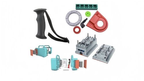
Professional DFM Engineering Review


Why Is DFM Analysis Important?
Without proper DFM analysis, companies often face unexpected challenges during tooling and production.
Common Problems Without DFM Review
| Design Issue | Manufacturing Consequence |
|---|---|
| Uneven wall thickness | Sink marks and warpage |
| Insufficient draft angle | Difficult ejection |
| Poor gate placement | Short shots and weld lines |
| Complex undercuts | Expensive mold structures |
| Weak rib design | Structural failure |
| Inadequate venting | Burn marks |
A professional DFM review can significantly reduce these risks before mold steel is cut.
Benefits of DFM Analysis
| Benefit | Result |
| Lower tooling risk | Fewer mold modifications |
| Improved product quality | Reduced defect rate |
| Faster development | Shorter project timeline |
| Lower production cost | Less scrap and rework |
| Better consistency | Stable mass production |
Wall Thickness Analysis
Wall thickness is one of the most critical factors in injection molding.
Uniform wall thickness promotes:
Smooth material flow
Consistent cooling
Balanced shrinkage
Reduced internal stress
When wall thickness varies significantly, thick sections cool slower than thin sections, leading to visible defects.
Recommended Wall Thickness Ranges
| Material | Recommended Thickness |
| ABS | 1.2 – 3.5 mm |
| PP | 0.8 – 3.8 mm |
| PC | 1.0 – 4.0 mm |
| PA66 | 0.8 – 3.0 mm |
| POM | 0.8 – 3.0 mm |
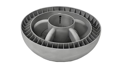
Wall Thickness Analysis Example

During DFM review, engineers identify thick areas that may require coring, redesign, or structural optimization.
Draft Angle Evaluation
Draft angles allow molded parts to release smoothly from the mold cavity.
Without sufficient draft:
Parts may stick to the core
Surface scratches can occur
Ejection force increases
Mold wear accelerates
Draft Angle Guidelines
| Surface Type | Recommended Draft |
| Smooth surfaces | 1°–2° |
| Textured surfaces | 3°–5° |
| Deep ribs | 1°–2° |
| Deep cavities | 2°–7° |
Draft Analysis Example

A DFM report highlights surfaces that may cause ejection problems and recommends modifications.
Rib and Boss Design Analysis
Ribs and bosses are widely used in plastic components to increase strength and provide fastening points.
However, improper design may cause:
Sink marks
Air traps
Flow restrictions
Warpage
Recommended Rib Design
| Feature | Recommendation |
| Rib Thickness | 50%–70% of wall thickness |
| Rib Height | Less than 3× wall thickness |
| Draft Angle | 0.5°–1.5° |
Rib and Boss Design Review

DFM engineers verify whether ribs and bosses provide adequate strength without creating molding defects.
Undercut Analysis
Undercuts are features that prevent direct mold opening.
Examples include:
Side holes
Snap-fit hooks
Internal locking features
Threaded details
These features often require:
Sliders
Lifters
Collapsible cores
Each additional mold mechanism increases tooling complexity and manufacturing cost.
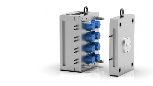
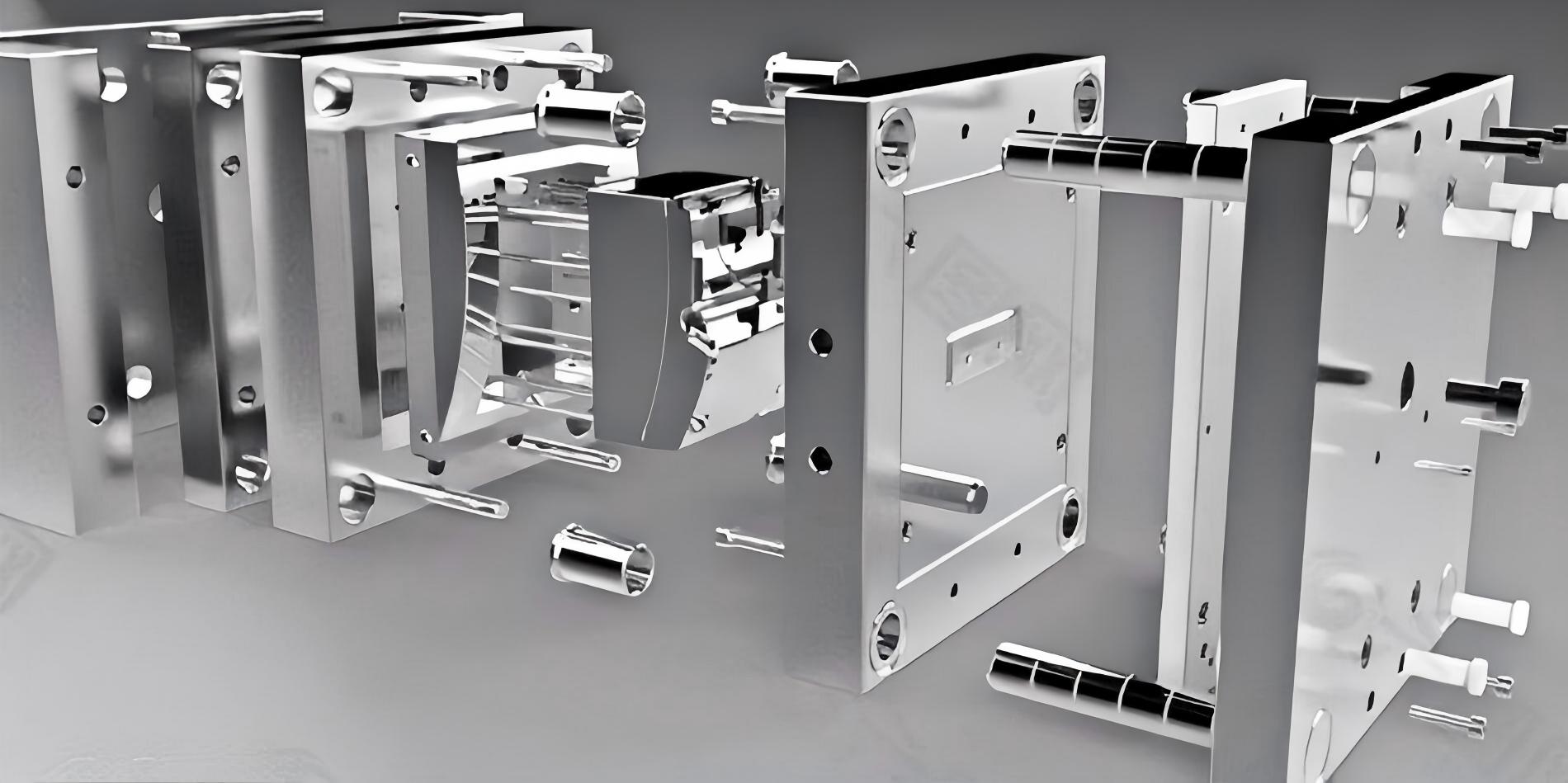
Slider and Lifter Structures


The DFM report evaluates whether undercuts can be simplified or eliminated to reduce tooling investment.
Gate Location Analysis
Gate placement directly affects filling performance and final part quality.
Poor gate location may result in:
Flow hesitation
Short shots
Visible weld lines
Air traps
Uneven shrinkage
Common Gate Types
| Gate Type | Typical Application |
| Edge Gate | General-purpose parts |
| Pin Gate | Multi-cavity molds |
| Submarine Gate | Automatic degating |
| Fan Gate | Large flat components |
| Hot Runner Gate | High-volume production |
Gate Design and Flow Pattern


Proper gate selection improves both appearance and dimensional stability.
Weld Line and Air Trap Analysis
During injection molding, multiple flow fronts may meet and form weld lines.
Weld lines often appear near:
Openings
Bosses
Snap-fit features
Structural supports
Potential consequences include:
Reduced mechanical strength
Visible cosmetic defects
Cracking under load
At the same time, trapped air can create burn marks and incomplete filling.
Mold Flow Defect Prediction


DFM reports use mold flow software to predict these issues before tooling begins.
Ejection and Cooling Analysis
Efficient ejection and cooling are essential for stable production.
DFM engineers evaluate:
Ejection System
Ejector pin locations
Stripper plate requirements
Thin-wall deformation risk
Cosmetic surface protection
Cooling System
Cooling channel layout
Temperature uniformity
Cycle time optimization
Warpage reduction
Cooling and Ejection Design


Optimized cooling often reduces cycle times by 10%–30%, improving production efficiency significantly.
Mold Flow Analysis in Modern DFM Reports
Today, many injection mold manufacturers include Mold Flow Analysis as part of the DFM package.
Typical simulation results include:
Fill time analysis
Pressure distribution
Clamp force prediction
Cooling efficiency
Weld line prediction
Air trap prediction
Warpage analysis
Mold Flow Simulation Results


These simulations help engineers optimize mold structure and processing parameters before production starts.
Conclusion
A professional Injection Molding DFM Report is one of the most valuable engineering tools in product development. It identifies manufacturing risks before mold construction, allowing designers and mold makers to optimize product geometry, improve production efficiency, and reduce overall costs.
From wall thickness analysis and draft evaluation to gate design, undercut assessment, cooling optimization, and mold flow simulation, every section of a DFM report contributes to a more reliable and cost-effective manufacturing process.
For companies developing plastic products, investing in a comprehensive DFM review before mold manufacturing is a proven strategy to shorten development cycles, minimize tooling risks, and achieve consistent production quality.